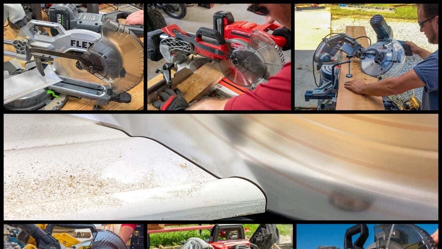
ICYMI: The Hottest Summer Tool and OPE Reviews for May
May kept us busy both in the shop and out in the field, with plenty of reviews and head-to-head testing […]

Professional Tool Reviews for Pros
Whether it’s cold hard facts or editorials by our professional staff, Pro Tool Reviews tells it like it is. We deliver a steady stream of power tool news for the construction and housing industry. Hopefully, this will keep you abreast of what’s happening in the construction industry. Our industry insights, articles, and editorials cover construction industry topics affecting professional tradesmen and business owners. If you’re in the construction business—no matter if you work on the jobsite or in the office—you need to know what trends and tools are shaping the work you do. Our team delivers both news & opinion to keep you up to speed and ahead of the curve. Because of this, you can be in the know with respect to OSHA regulations, modern construction methods, and therefore any other developments taking place that could affect your work. While our power tool reviews and hand tool reviews let you know what’s hot from the manufacturers. For everything else, you’ll want to stay tuned to our news and opinion editorial coverage.
May kept us busy both in the shop and out in the field, with plenty of reviews and head-to-head testing […]
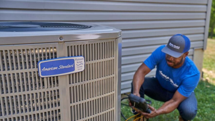
In partnership with American Standard Heating and Air Conditioning Thinking about upgrading your home HVAC system with a new heat […]
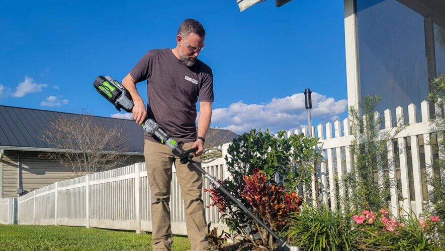
Loading and feeding trimmer line are two of the biggest pain points when you’re using a string trimmer. We’ve seen […]

In partnership with Greenworks Commercial It’s hard to believe 10 years have already gone by since Greenworks Commercial first launched […]

Dash cameras are increasingly popular among drivers, and many corporations install them on all their vehicles. Some vehicles, like Teslas, […]
April started off, like we do every year, with our April Fool’s Day spoof articles. However, the rest of the […]
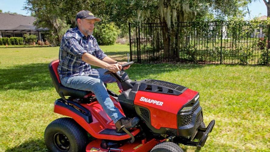
In partnership with Snapper Mowers The first riding mower my family owned was a classic Snapper rear-engine model back in […]

When the older generations of tradesmen age out of the trades and retire, who will fill the gap? For upcoming […]
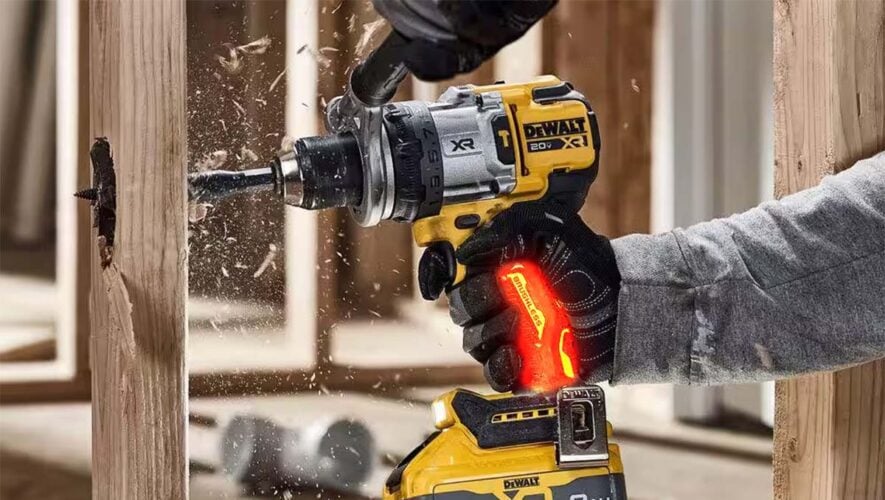
Milwaukee, WI – DeWalt made waves at the National Hardware Show this year when it unveiled the DCD9999HW, a 20V […]

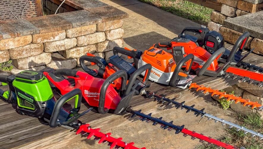
We’ve reviewed a lot of outdoor power equipment in this office. Gas-powered, battery-powered, even that one solar-powered automatic weeder that […]